
Fleet Services Directory
USA & Canada
Aftermarket Fleet Service Providers
Free to Use. Free to List Your Company.
Find Your Partner
Search for fleet installers and fleet services near you. Fleet or personal vehicles, it does not matter. Get it done right.
Professionals know how to get things done right and quickly. Professional installers can handle local, regional or national deployments of software or hardware.
Find Your Partner
Search for fleet installers and fleet services near you. Fleet or personal vehicles, it does not matter. Get it done right.

 ASSET BY TYPE (21)
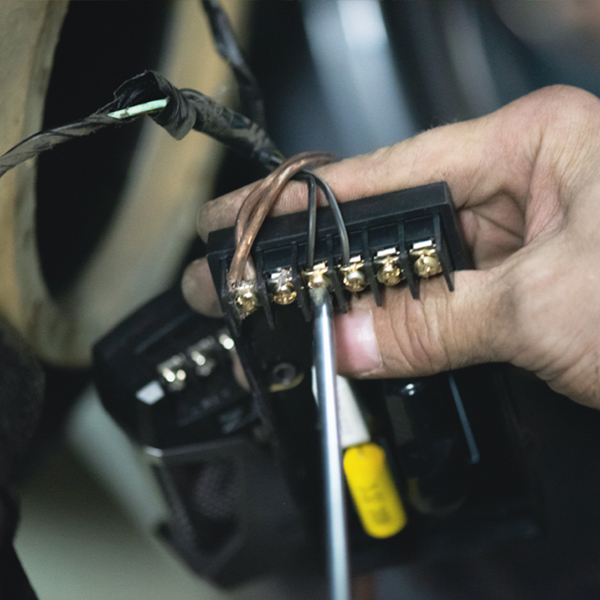 ELECTRONICS (19)
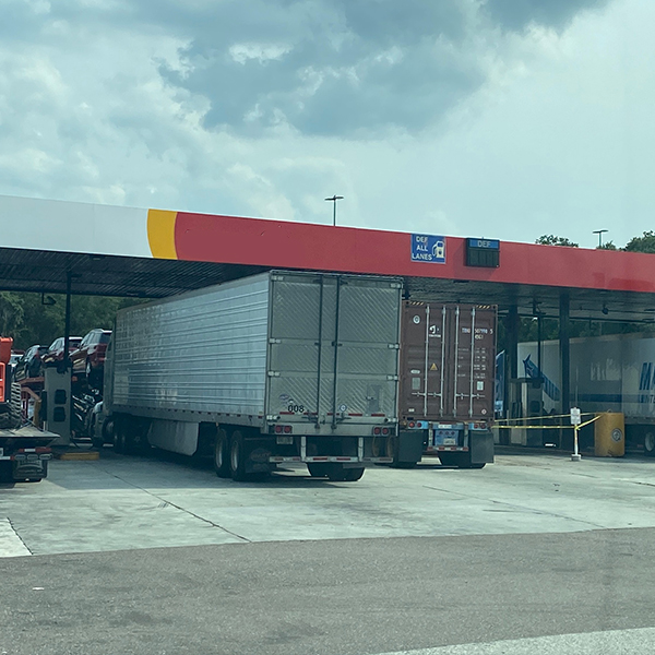 FLEET SERVICE CENTERS (7)
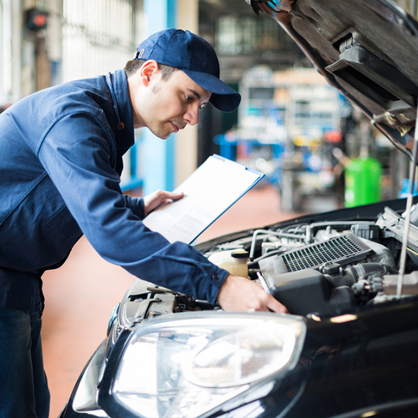 MOBILE MAINTENANCE (8)
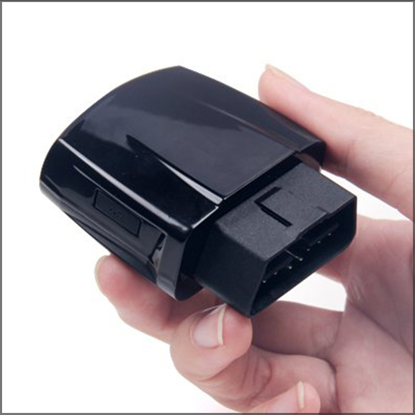 PRODUCT CERTIFIED TECHS (18)
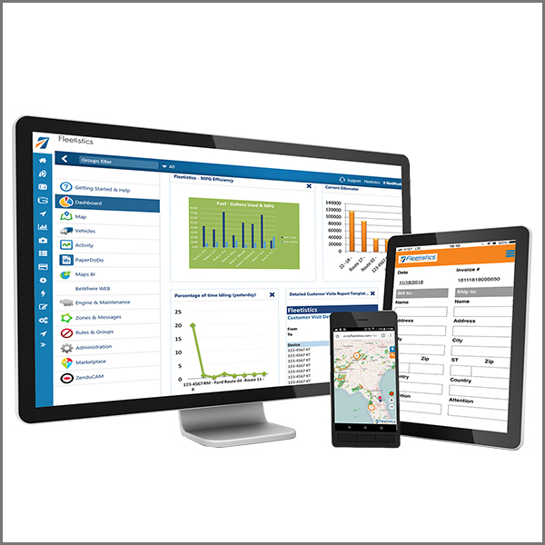 SOFTWARE (3)
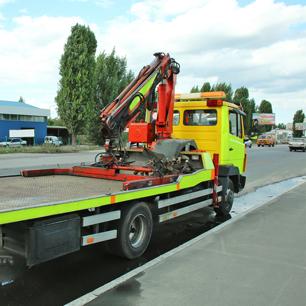 UPFITTERS (1)
- ASSET BY TYPE (21)
- ELECTRONICS (19)
- FLEET SERVICE CENTERS (7)
- MOBILE MAINTENANCE (8)
- PRODUCT CERTIFIED TECHS (18)
- SOFTWARE (3)
- UPFITTERS (1)
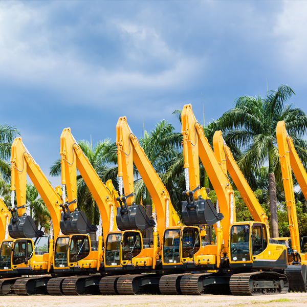
Vehicle Installers Includes: GPS installers, fuel cards, GPS tracking, Dashcams, Fleet maintenance, Towing, Roadside repair, Repair facilities, Truck stops, Truck parts, Fleet insurance, Software, ELD, etc.
Vehicle Installers Includes: GPS installers, fuel cards, GPS tracking, Dashcams, Fleet maintenance, Towing, Roadside repair, Repair facilities, Truck stops, Truck parts, Fleet insurance, Software, ELD, etc.
Electronics
GPS, Dashcams, Sensors
Find vehicle installers to install aftermarket GPS tracking, telematics, dashcams, stereos, backup cameras, scales, PTOs and auxiliaries.
Stationary or mobile, vehicle installer professionals get it done.
Fleet Management
Store Service Centers
Manage your fleet more efficiently with the help of cloud services for fleet maintenance, lease management, tablet setup, dispatching, insurance, tire management, purchasing and more. Services provide a full range of opportunities.
Maintenance & Repair
Vehicles, Assets, Equipment
When you are on the road and need help, roadside repair providers are the ones to call. From local providers in rural areas, to national contracted service providers, getting your truck or vehicle back on the road is the top priority.
Grow your fleet installation business
List each location with a physical presence, free!